网络基础知识到后面,基本上就是应用层上干,这样的事情实在太多了,毕竟依赖网络的软件总是无穷无尽的.
大致看一下这个简单的网络规划.
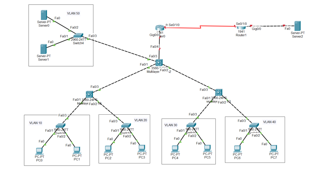
其中PC0/PC1是VLAN10客户端,PC2/PC3是VLAN20客户端,PC4/PC5是VLAN30客户端,PC6/PC7是VLAN40客户端,Server0/Server1是内部服务器,属于VLAN50,上面说到的这些都要可以访问外网.且需要使用适当ACL进行权限管理.
按逻辑上说,下面的2960-24TT全试试接入层交换机,没路由功能的傻交换机,只能进行VLAN划分,汇聚层由两个3560-24PS组成,属于三层交换机,提供VLAN间通信,路由选择,DHCP服务,核心层由另一个三层交换机提供,主要进行路由选择,之后就是路由器,这里用的是1941进行模拟.
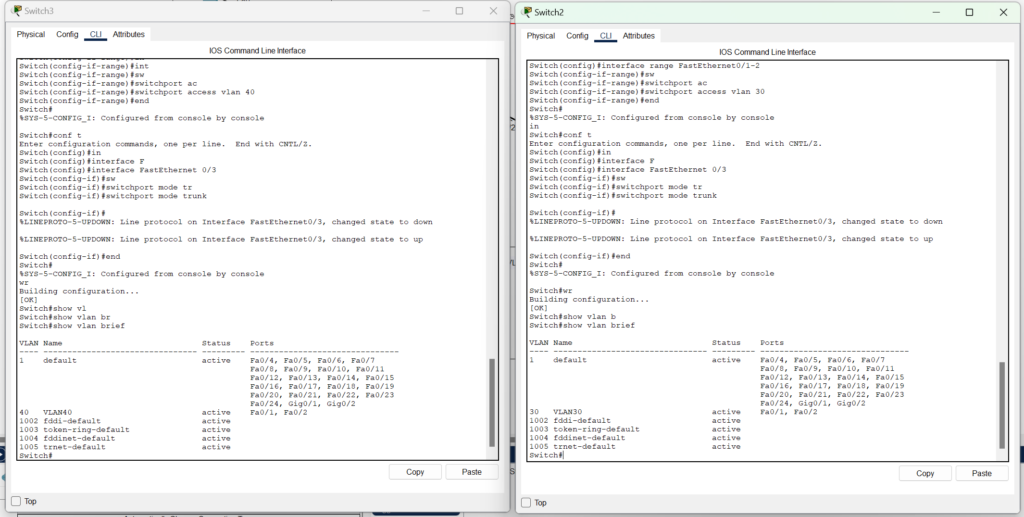
给4个接入层接入层交换机配置VLAN,上游端口为Trunk,下游端口为VLAN10/20/30/40,为什么上游配置成Trunk,这样他发给上游时候就带着ID了,配置参考.
Switch>en
Switch#conf t
Enter configuration commands, one per line.  End with CNTL/Z.
Switch(config)#vlan 10
Switch(config-vlan)#name VLAN10
Switch(config-vlan)#end
Switch#conf t
Enter configuration commands, one per line.  End with CNTL/Z.
Switch(config)#interface range Fa0/1-2
Switch(config-if-range)#switchport access vlan 10
Switch(config-if-range)#end
Switch#
%SYS-5-CONFIG_I: Configured from console by console
Switch#conf t
Enter configuration commands, one per line.  End with CNTL/Z.
Switch(config)#interface FastEthernet 0/3
Switch(config-if)#switchport mode trunk
Switch(config-if)#end
Switch#
%SYS-5-CONFIG_I: Configured from console by console
Switch#show vlan brief

VLAN Name                             Status    Ports
---- -------------------------------- --------- -------------------------------
1    default                          active    Fa0/4, Fa0/5, Fa0/6, Fa0/7
                                                Fa0/8, Fa0/9, Fa0/10, Fa0/11
                                                Fa0/12, Fa0/13, Fa0/14, Fa0/15
                                                Fa0/16, Fa0/17, Fa0/18, Fa0/19
                                                Fa0/20, Fa0/21, Fa0/22, Fa0/23
                                                Fa0/24, Gig0/1, Gig0/2
10   VLAN10                           active    Fa0/1, Fa0/2
1002 fddi-default                     active
1003 token-ring-default               active
1004 fddinet-default                  active
1005 trnet-default                    active
Switch#
另外三个交换机也是这么配置,并反复确认配置正确.
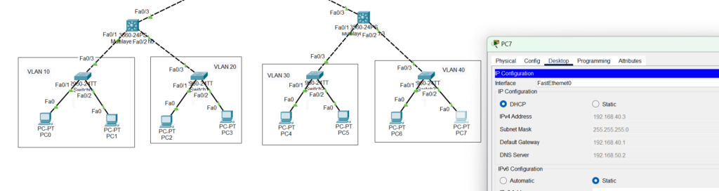
其中VLAN10的IP范围192.168.10.0/24,VLAN20的IP范围是192.168.20.0/24,VLAN30的IP范围是192.168.30.0/24,VLAN40的IP范围是192.168.40.0/24,他们各自网关都是192.168.X.1/24.为了简化,不同交换机之间用RIPv2交换路由.
先新建两个VLAN接口,然后分配配上对应的IP地址.
Switch>en
Switch#conf t
Enter configuration commands, one per line.  End with CNTL/Z.
Switch(config)#vlan 10
Switch(config-vlan)#name VLAN10
Switch(config-if)#ip address 192.168.10.1 255.255.255.0
Switch(config-vlan)#end
Switch#
%SYS-5-CONFIG_I: Configured from console by console
conf t
Enter configuration commands, one per line.  End with CNTL/Z.
Switch(config)#vlan 20
Switch(config-vlan)#name VLAN20
Switch(config-if)#ip address 192.168.20.1 255.255.255.0
Switch(config-vlan)#end
Switch#
%SYS-5-CONFIG_I: Configured from console by console
Switch#wr
Building configuration...
[OK]
Switch#show vlan brief

VLAN Name                             Status    Ports
---- -------------------------------- --------- -------------------------------
1    default                          active    Fa0/3, Fa0/4, Fa0/5, Fa0/6
                                                Fa0/7, Fa0/8, Fa0/9, Fa0/10
                                                Fa0/11, Fa0/12, Fa0/13, Fa0/14
                                                Fa0/15, Fa0/16, Fa0/17, Fa0/18
                                                Fa0/19, Fa0/20, Fa0/21, Fa0/22
                                                Fa0/23, Fa0/24, Gig0/1, Gig0/2
10   VLAN10                           active
20   VLAN20                           active
1002 fddi-default                     active
1003 token-ring-default               active
1004 fddinet-default                  active
1005 trnet-default                    active
Switch#show interfaces vlan10
Vlan10 is up, line protocol is up
  Hardware is CPU Interface, address is 0040.0bdb.5601 (bia 0040.0bdb.5601)
  Internet address is 192.168.10.1/24
  MTU 1500 bytes, BW 100000 Kbit, DLY 1000000 usec,
     reliability 255/255, txload 1/255, rxload 1/255
  Encapsulation ARPA, loopback not set
  ARP type: ARPA, ARP Timeout 04:00:00
  Last input 21:40:21, output never, output hang never
  Last clearing of "show interface" counters never
  Input queue: 0/75/0/0 (size/max/drops/flushes); Total output drops: 0
  Queueing strategy: fifo
  Output queue: 0/40 (size/max)
  5 minute input rate 0 bits/sec, 0 packets/sec
  5 minute output rate 0 bits/sec, 0 packets/sec
     1682 packets input, 530955 bytes, 0 no buffer
     Received 0 broadcasts (0 IP multicast)
     0 runts, 0 giants, 0 throttles
     0 input errors, 0 CRC, 0 frame, 0 overrun, 0 ignored
     563859 packets output, 0 bytes, 0 underruns
     0 output errors, 23 interface resets
     0 output buffer failures, 0 output buffers swapped out

Switch#show interfaces vlan20
Vlan20 is up, line protocol is up
  Hardware is CPU Interface, address is 0040.0bdb.5602 (bia 0040.0bdb.5602)
  Internet address is 192.168.20.1/24
  MTU 1500 bytes, BW 100000 Kbit, DLY 1000000 usec,
     reliability 255/255, txload 1/255, rxload 1/255
  Encapsulation ARPA, loopback not set
  ARP type: ARPA, ARP Timeout 04:00:00
  Last input 21:40:21, output never, output hang never
  Last clearing of "show interface" counters never
  Input queue: 0/75/0/0 (size/max/drops/flushes); Total output drops: 0
  Queueing strategy: fifo
  Output queue: 0/40 (size/max)
  5 minute input rate 0 bits/sec, 0 packets/sec
  5 minute output rate 0 bits/sec, 0 packets/sec
     1682 packets input, 530955 bytes, 0 no buffer
     Received 0 broadcasts (0 IP multicast)
     0 runts, 0 giants, 0 throttles
     0 input errors, 0 CRC, 0 frame, 0 overrun, 0 ignored
     563859 packets output, 0 bytes, 0 underruns
     0 output errors, 23 interface resets
     0 output buffer failures, 0 output buffers swapped out

Switch#
配置DHCP服务器.
Switch#conf t
Enter configuration commands, one per line.  End with CNTL/Z.
Switch(config)#ip dhcp excluded-address 192.168.10.1
Switch(config)#ip dhcp excluded-address 192.168.20.1
Switch(config)#ip dhcp pool VLAN10
Switch(dhcp-config)#network 192.168.10.0 255.255.255.0
Switch(dhcp-config)#default-router 192.168.10.1
Switch(dhcp-config)#dns-server 192.168.50.2
Switch(dhcp-config)#exit
稍微检查一下配置.
Switch#show running-config
Building configuration...

Current configuration : 1604 bytes
!
version 12.2(37)SE1
no service timestamps log datetime msec
no service timestamps debug datetime msec
no service password-encryption
!
hostname Switch
!
!
!
ip dhcp excluded-address 192.168.10.1
ip dhcp excluded-address 192.168.20.1
!
ip dhcp pool VLAN10
 network 192.168.10.0 255.255.255.0
 default-router 192.168.10.1
 dns-server 192.168.50.2
ip dhcp pool VLAN20
 network 192.168.20.0 255.255.255.0
 default-router 192.168.20.1
 dns-server 192.168.50.2
开启三层路由功能并配置RIPv2,设置上游IP为192.168.1.1/30.
Switch(config)#ip routing
Switch(config)#interface FastEthernet 0/3
Switch(config-if)#no switchport
Switch(config-if)#
%LINEPROTO-5-UPDOWN: Line protocol on Interface FastEthernet0/3, changed state to down

%LINEPROTO-5-UPDOWN: Line protocol on Interface FastEthernet0/3, changed state to up

Switch(config-if)#ip address 192.168.1.1 255.255.255.252
Switch(config-if)#exit
Switch(config)#router rip
Switch(config-router)#ver
Switch(config-router)#version 2
Switch(config-router)#networ
Switch(config-router)#network 192.168.10.0
Switch(config-router)#network 192.168.20.0
Switch(config-router)#network 192.168.1.0
Switch(config-router)#no au
Switch(config-router)#no auto-summary
Switch(config-router)#exit
Switch(config)#ip route 0.0.0.0 0.0.0.0 192.168.1.2
为什么不用配置接口,因为不配时候就是Trunk,最后设置PC机为DHCP,让时间流逝一下.
Switch#show ip dhcp binding
IP address       Client-ID/              Lease expiration        Type
                 Hardware address
192.168.10.2     0010.11A9.A785           --                     Automatic
192.168.10.3     0001.C72D.D03A           --                     Automatic
192.168.20.2     00D0.5892.6220           --                     Automatic
192.168.20.3     0009.7C8D.AD80           --                     Automatic
Switch#
另一个交换机也是类似配置.上游端口配192.168.2.1/30,VLAN IP格式和之前约定一样,RIP也改成自己可直达的段,到目前所有PC应该可以获得IP并和三层交换机通信,但仍不能跨越VLAN.
配置核心交换机,核心交换机内部配置了一些VLAN50的内部网,另外的Fa0/1,Fa0/2,Fa0/4都是属于"走到外面",所以关闭他们的交换功能,并配置IP地址,部分配置结果参考.
ip routing
no ip domain-lookup
interface FastEthernet0/1
no switchport
ip address 192.168.1.2 255.255.255.252
duplex auto
speed auto
!
interface FastEthernet0/2
no switchport
ip address 192.168.2.2 255.255.255.252
duplex auto
speed auto
!
interface FastEthernet0/3
!
interface FastEthernet0/4
no switchport
ip address 192.168.3.1 255.255.255.252
duplex auto
speed auto
!
interface Vlan1
no ip address
shutdown
!
interface Vlan50
mac-address 0060.4725.4801
ip address 192.168.50.1 255.255.255.0
!
router rip
network 192.168.1.0
network 192.168.2.0
network 192.168.3.0
network 192.168.50.0
no auto-summary
!
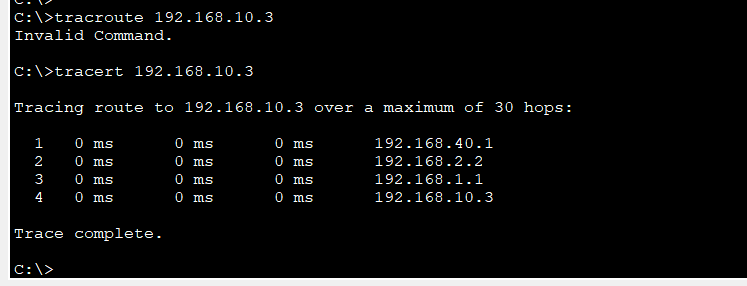
ip route 0.0.0.0 0.0.0.0 192.168.3.2 过一段时间后,他们应该能正常通信了.
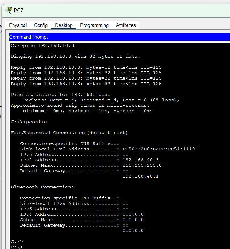
看路径也符合我们设计.
把进入服务器的那个交换机配置一个VLAN50,其他配置类似接入层的交换机配置,配置结果如下不再重复.
Switch#show vlan brief
VLAN Name Status Ports
---- -------------------------------- --------- -------------------------------
1 default active Fa0/4, Fa0/5, Fa0/6, Fa0/7
Fa0/8, Fa0/9, Fa0/10, Fa0/11
Fa0/12, Fa0/13, Fa0/14, Fa0/15
Fa0/16, Fa0/17, Fa0/18, Fa0/19
Fa0/20, Fa0/21, Fa0/22, Fa0/23
Fa0/24, Gig0/1, Gig0/2
50 VLAN50 active Fa0/1, Fa0/2
1002 fddi-default active
1003 token-ring-default active
1004 fddinet-default active
1005 trnet-default active
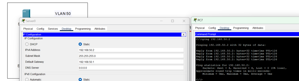
Switch#给核心层的Fa0/3不用配置,默认为Trunk,需要配置VLAN50,并附加IP地址192.168.50.1/24,接着等生效.Server0配置IP为192.158.50.2/24,Server1配置为192.168.50.3/24,确保可以访问.
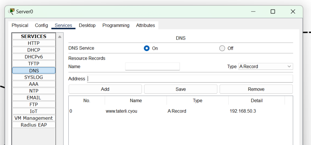
给Server0配置DNS.
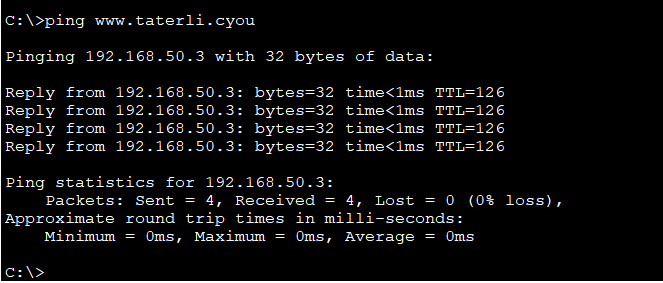
测试可解释.
现在可以开始配置我方路由,即Route0,大致配置如下.
Router>en
Router#conf t
Enter configuration commands, one per line.  End with CNTL/Z.
Router(config)#interface GigabitEthernet 0/0
Router(config-if)#ip address 192.168.3.2 255.255.255.252
Router(config-if)#no shutdown
%LINK-5-CHANGED: Interface GigabitEthernet0/0, changed state to up
%LINEPROTO-5-UPDOWN: Line protocol on Interface GigabitEthernet0/0, changed state to up
Router(config-if)#exit
Router(config)#interface Serial 0/1/0
Router(config-if)#ip address 200.1.1.1 255.255.255.252
Router(config-if)#no shutdown
%LINK-5-CHANGED: Interface Serial0/1/0, changed state to down
Router(config-if)#exit
Router(config)#rou
Router(config)#router rip
Router(config-router)#network 192.168.3.0
Router(config-router)#network 200.1.1.0
Router(config-router)#no auto-summary
Router(config-router)#exit
Router(config)#ip route 0.0.0.0 0.0.0.0 200.1.1.2
Router(config)#interface GigabitEthernet 0/0
Router(config-if)#ip nat inside
Router(config-if)#exit
Router(config)#interface Serial 0/1/0
Router(config-if)#ip nat outside
Router(config-if)#exit
Router(config)#ip nat pool napt-p
Router(config)#ip nat pool napt-p
Router(config)#ip nat pool napt-pool 200.1.1.1 200.1.1.1 netma
Router(config)#ip nat pool napt-pool 200.1.1.1 200.1.1.1 netmask 255.255.255.252
Router(config)#access-list 1 permit 192.168.10.0 0.0.0.255
Router(config)#access-list 1 permit 192.168.20.0 0.0.0.255
Router(config)#access-list 1 permit 192.168.30.0 0.0.0.255
Router(config)#access-list 1 permit 192.168.40.0 0.0.0.255
Router(config)#ip nat inside source list 1 pool napt-pool overload
Router(config)#exit
Router#
%SYS-5-CONFIG_I: Configured from console by console
给内部接口配置192.168.3.2/30,给外部接口配置200.1.1.1/30,这里200.1.1.1是外网IP,也使用RIP建立路由树,并配置一个NAT,出口IP只有200.1.1.1,允许的范围只有VLAN10,20,30,40,不包含VLAN50.
然后配置ISP端路由器,模拟是远端的设备.
Router#
Router#configure terminal
Enter configuration commands, one per line.  End with CNTL/Z.
Router(config)#interface Serial0/1/0
Router(config-if)#
Router(config-if)#exit
Router(config)#interface GigabitEthernet0/0
Router(config-if)#ip address 218.75.230.1 255.255.255.0
Router(config-if)#no shutdown
Router(config-if)#
%LINK-5-CHANGED: Interface GigabitEthernet0/0, changed state to up

%LINEPROTO-5-UPDOWN: Line protocol on Interface GigabitEthernet0/0, changed state to up

Router(config-if)#exit
Router(config)#interface Serial0/1/0
Router(config-if)#ip address 200.1.1.2 255.255.255.252
Router(config-if)#no shutdown
Router(config-if)#
%LINK-5-CHANGED: Interface Serial0/1/0, changed state to up
配置互联网上服务器,开启一个Web服务,并在内部DNS服务器新增条目.
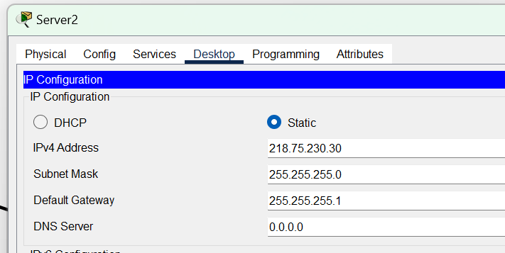
最后测试结果,内部服务器不可以访问外部,内部客户端通过NAPT改写访问外部.这些实验都是很简单的就不再截图记录了.
总结:这里也没用到扩展ACL规则,也没演示6to4和IPSec隧道,这些网上说的内容特别多的了,就不再重复,通过这个实验,基本也熟悉一些比较简单的网络架构实验.