Pico模块有3个ADC通道,固定在4个引脚上,总共5个通道,其中一个内部通道即温度传感器,还有专用的ADC_VREF引脚,主要特性如下:
- SAR ADC (现在的单片机上除了仪表系的,基本都是SAR ADC了!)
- 500 kSPS (独立48MHz时钟,因此是固定的,对比来看,STM32G0入门级芯片是2.5 MSPS,差距5倍.)
- 12Bit (9.5 ENOB) (对比STM32G0入门级芯片是10.2 ENOB)
- 5个输入源 (GPIO26,GPIO27,GPIO28,GPIO29,内部温度传感器) (和传统单片机数量差远了.)
- 4个坑位采样FIFO (应该是标配的吧,容量不大不小.)
- 中断/DMA支持 (标配,不用说.)
- 采样一次停止/连续采样不停止 (标配,不用说.)
- 自由模式下定时器控制采样速率 (不是采样率,是采样速率,即延迟多久之后还是按照500 kSPS采样,不能从降低采样率来获得更高的精度,不过可以避免多通道扫描的干扰,控制寄存器DIV如果设置到47999,则看起来才1 kSPS,但是要知道大多数芯片One-Shot模式也支持采样率可控.)
- 自由模式下多通道循环采样 (标配,不用说,实际上大多数芯片还会配备可编程顺序.)
- 自动缩减至8位 (竟然是用12位右移来做的,浪费采样时间啊,正常芯片都是采样8B自己停下来.)
- 内置温度传感器固定公式 (居然没有出厂校正,什么玩意.)
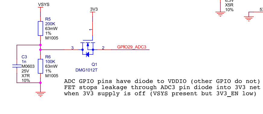
- 没有内置VREF,因此不能反推AVCC电压. (如果可以反推可以减少误差.)
在Pico板子上,GPIO29即ADC/4通道是用来测量VSYS/3电压的.
现在修改hello_adc来测量VSYS电压.
/**
* Copyright (c) 2020 Raspberry Pi (Trading) Ltd.
*
* SPDX-License-Identifier: BSD-3-Clause
*/
#include <stdio.h>
#include "pico/stdlib.h"
#include "hardware/gpio.h"
#include "hardware/adc.h"
int main() {
stdio_init_all();
printf("ADC Example, measuring GPIO29\n");
adc_init();
// Make sure GPIO is high-impedance, no pullups etc
adc_gpio_init(29);
// Select ADC input 3 (GPIO29)
adc_select_input(3);
while (1) {
// 12-bit conversion, assume max value == ADC_VREF == 3.3 V
const float conversion_factor = 3.3f / (1 << 12);
uint16_t result = adc_read();
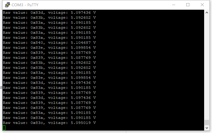
printf("Raw value: 0x%03x, voltage: %f V\n", result, 3 * result * conversion_factor);
sleep_ms(500);
}
}
得到测量结果.
如果需要采样多个通道,需要不断调用adc_select_input切换通道,说明,他们是共享一个ADC外设的.具体可以看joystick_display例子.
如果我们要测量温度传感器,需要先使能温度传感器.
/**
* Copyright (c) 2020 Raspberry Pi (Trading) Ltd.
*
* SPDX-License-Identifier: BSD-3-Clause
*/
#include <stdio.h>
#include "pico/stdlib.h"
#include "hardware/gpio.h"
#include "hardware/adc.h"
int main() {
stdio_init_all();
printf("ADC Example, measuring GPIO29\n");
adc_init();
adc_set_temp_sensor_enabled(true);
adc_select_input(4);
while (1) {
// 12-bit conversion, assume max value == ADC_VREF == 3.3 V
const float conversion_factor = 3.3f / (1 << 12);
uint16_t result = adc_read();
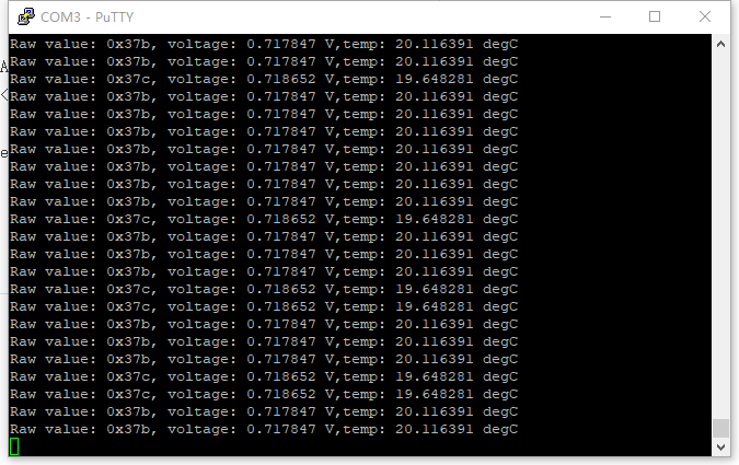
printf("Raw value: 0x%03x, voltage: %f V,temp: %f degC\n", result, result * conversion_factor,27 - (result * conversion_factor - 0.706)/0.001721);
sleep_ms(500);
}
}
但是现在温度计实测23度,芯片内部传感器比环境还冷?
最后看看连续采样,即Free Run,这里的Free Run只能按特定顺序(一个或多个通道)扫描,并不能编程顺序.通过adc_set_round_robin的5个bit(BIT0 - BIT5)来配置扫描,数据存入FIFO后然后人为取出,为什么要存入FIFO是因为数据进来后立马有新的采样,如果用传统read,可能会导致数据消失.
adc_fifo_setup(true, false, 0, false, false);
adc_set_round_robin(0x0F);
adc_run(true);
for (int i = 0; i < count; i = i + 1)
    buf[i] = adc_fifo_get_blocking();
adc_run(false);
adc_fifo_drain();
首先用adc_fifo_setup初始化,然后有函数adc_fifo_get_blocking,当然也有adc_fifo_get,前者会查询标志位,等数据,堵塞CPU,后者直接读取,需要用户自己判断数据是不是来了,可以通过adc_fifo_get_level查询现在数据有多满,也可以用adc_fifo_is_empty查询数据是不是完全没有,最后用adc_fifo_drain清理FIFO队列,可能会丢掉最后几个数据,不过那都是不要紧的数据.
adc_fifo_setup基本是配置整个寄存器功能的,具体描述如下:
/*! \brief Setup the ADC FIFO
 *  \ingroup hardware_adc
 *
 * FIFO 最多可以存4个样本,存满的话新数据就没法进来.
 *
 * \param en FIFO使能,启用后结果可以存入FIFO.
 * \param dreq_en 当FIFO包含数据且到达dreq_thresh阈值,请求DMA.
 * \param dreq_thresh 参考dreq_en.
 * \param err_in_fifo FIFO的BIT15(最高位)包含样本错误标志.
 * \param byte_shift 把12位样本缩减成8位,但是实际采样速度没变.
 */
static inline void adc_fifo_setup(bool en, bool dreq_en, uint16_t dreq_thresh, bool err_in_fifo, bool byte_shift);
这种采样方式我想到的就是采样很多遍,然后进行平均或者其他什么信号处理...
温度传感器的,有相关代码可以参考一下吗?