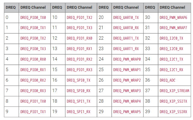
标配的外设,RP2040的DMA是挂在AHB-Lite上的,在M0内核范畴算比较高性能的总线了,支持的触发源有39个,基本上所有外设源都有了.
总共有12个CH,通过仲裁(方法未知)获得总线使用权,支持8B/16B/32B传输,支持中断时候改配置,没有半传输中断(可以用环形缓冲另类实现),有传输完成中断,支持可编程区块传输(即DMA控制DMA),因为内存分区比较散,所以内存间传输还有讲究,但这里不深入讨论内存分布问题,后续再说.
DMA相关函数和方法比较多,但是操作起来其实很简单,总结起来分为几个:
- 查找闲置通道/标记通道使用/取消标记通道占用
- 设置源地址/目标地址自增
- 设置传输请求/设置传输目标
- 等待传输完成/中断响应
- 地址包络/字节翻转/嗅探支持
由于DMA通常不会单独工作,所以这里也只能初步看看.
// Data will be copied from src to dst
const char src[] = "Hello, world! (from DMA)";
char dst[count_of(src)];

int main() {
    stdio_init_all();

    // Get a free channel, panic() if there are none
    int chan = dma_claim_unused_channel(true);

    // 8 bit transfers. Both read and write address increment after each
    // transfer (each pointing to a location in src or dst respectively).
    // No DREQ is selected, so the DMA transfers as fast as it can.

    dma_channel_config c = dma_channel_get_default_config(chan);
    channel_config_set_transfer_data_size(&c, DMA_SIZE_8);
    channel_config_set_read_increment(&c, true);
    channel_config_set_write_increment(&c, true);

    dma_channel_configure(
        chan,          // Channel to be configured
        &c,            // The configuration we just created
        dst,           // The initial write address
        src,           // The initial read address
        count_of(src), // Number of transfers; in this case each is 1 byte.
        true           // Start immediately.
    );

    // We could choose to go and do something else whilst the DMA is doing its
    // thing. In this case the processor has nothing else to do, so we just
    // wait for the DMA to finish.J
    dma_channel_wait_for_finish_blocking(chan);

    // The DMA has now copied our text from the transmit buffer (src) to the
    // receive buffer (dst), so we can print it out from there.
    puts(dst);
}
则例的逻辑是申请一个通道,然后设置传输大小,自增,然后立即开始,然后查询标志,类似完成CPU的memcpy,但是他由DMA完成,速度不如memcpy,但是可以释放CPU来干别的事情.
为了达到释放CPU的目的.需要使用中断,我们从hello dma上开始改,也很容易实现DMA中断.
第一步添加IRQ头文件:
#include "hardware/irq.h"新建处理Handle,并清除标志位,多源中断函数还应该判断标志位.
void dma_handler() {
    // Clear the interrupt request.
    dma_hw->ints0 = 1u << chan;
    // Print dst
    puts(dst);
}
把查询代码改成中断.
// Tell the DMA to raise IRQ line 0 when the channel finishes a block
dma_channel_set_irq0_enabled(chan, true);

// Configure the processor to run dma_handler() when DMA IRQ 0 is asserted
irq_set_exclusive_handler(DMA_IRQ_0, dma_handler);
irq_set_enabled(DMA_IRQ_0, true);

while (true){}
修改后的整体代码:
/**
 * Copyright (c) 2020 Raspberry Pi (Trading) Ltd.
 *
 * SPDX-License-Identifier: BSD-3-Clause
 */

// Use the DMA to copy data between two buffers in memory.

#include <stdio.h>
#include "pico/stdlib.h"
#include "hardware/dma.h"
#include "hardware/irq.h"

// Data will be copied from src to dst
const char src[] = "Hello, world! (from DMA)";
char dst[count_of(src)];

int chan = 0;

void dma_handler() {
    // Clear the interrupt request.
    dma_hw->ints0 = 1u << chan;
    // Print dst
    puts(dst);
}

int main() {
    stdio_init_all();

    // Get a free channel, panic() if there are none
    chan = dma_claim_unused_channel(true);

    // 8 bit transfers. Both read and write address increment after each
    // transfer (each pointing to a location in src or dst respectively).
    // No DREQ is selected, so the DMA transfers as fast as it can.

    dma_channel_config c = dma_channel_get_default_config(chan);
    channel_config_set_transfer_data_size(&c, DMA_SIZE_8);
    channel_config_set_read_increment(&c, true);
    channel_config_set_write_increment(&c, true);

    dma_channel_configure(
        chan,          // Channel to be configured
        &c,            // The configuration we just created
        dst,           // The initial write address
        src,           // The initial read address
        count_of(src), // Number of transfers; in this case each is 1 byte.
        true           // Start immediately.
    );

    // Tell the DMA to raise IRQ line 0 when the channel finishes a block
    dma_channel_set_irq0_enabled(chan, true);

    // Configure the processor to run dma_handler() when DMA IRQ 0 is asserted
    irq_set_exclusive_handler(DMA_IRQ_0, dma_handler);
    irq_set_enabled(DMA_IRQ_0, true);

    while (true){}
}
这样就变成中断驱动了.
最后最难的就是控制传输,其实这个其他芯片也有(猜测),因为他是通过修改DMA CTRL寄存器实现的.这里说下,寄存器填充总共有4个模式寄存器,他们意义分别不同.
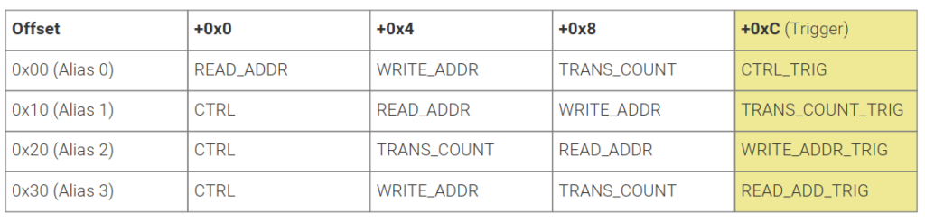
比如像官方例子里面,使用了Alias 3模式,CTRL和WRITE_ADDR是规定的,WRITE地址是串口,但是TRANS_COUNT和READ_ADDR是可变的,所以每次传输TRANS_COUNT和READ_ADDR,传输了READ_ADDR后就会触发真正的DMA传输,当开始之后,整个队列传输完成,才会中断.通过这种方式,可以实现PING-PONG-BUF,即队列永远不NULL,然后数据不断来回填充...
例子上设置Alias 3,从TRANS_COUNT开始设置2个WORD.
dma_channel_configure(
    ctrl_chan,
    &c,
    &dma_hw->ch[data_chan].al3_transfer_count, // Initial write address
    &control_blocks[0],                        // Initial read address
    2,                                         // Halt after each control block
    false                                      // Don't start yet
);
然后最后只需要开始控制CH,就会自动按照自己规划的列表去传输了.